
- #Microsoft sidewinder force feedback pro drivers
- #Microsoft sidewinder force feedback pro software
- #Microsoft sidewinder force feedback pro code
- #Microsoft sidewinder force feedback pro Pc
#Microsoft sidewinder force feedback pro code
Then, I plan to wire up some additional buttons on the grip, and modify the code to register those. Next steps are to open up the grip itself, then either clean or replace the switches.
#Microsoft sidewinder force feedback pro software
Force feedback seems to be working, test software works, although I haven't been able to test it in an actual game yet. The buttons on the grip are a very worn, needing a lot of force to push. All the axes are still working, buttons on the base still work. For the 12v power, I found a 12v 1.5A adapter that came from a broken WD external drive (hurray for hoarding ).įor now, the stick sort of works. For now, the wires come out of the stick and are plugged into the breadboard. Here's the assembled adapter, plugged into USB. That's 12v power and GND for the force feedback system, the barrel connector broke off years ago, and the power brick that came with the stick got lost sometime ago. It's tucked inside the base for now, but I may cut it even shorter if it bothers me. Also shown is what remains of the original DB15 cable. I used a Cat5 cable plus 2 more wires and pushed the ends into the 11 pin header. Here's the wiring I did to the mainboard. The throttle axes is detected using a LED on an arm connected to the throttle knob. In the center you can make out the 2 leds that show the X,Y and twist axes. Due to the size of the motors, the stick base itself had a lot of empty space. I actually cut off the DB15 cord, intending to wire the adapter directly to the board and mount it internally. Removing those lets me take the whole board out for wiring. (note: this picture was actually taken after I did the wiring and started reassembly).Ģ screws held the board in place, the sensors, buttons, lights and motors are plugged in to the board using headers. Here's the main board, and a view of the feedback motors. The whole bottom plate comes off, with no boards or wires stuck to it, which made it easier to work on. 2 of the screws are hidden under rubber feet at 12 o'clock, and lower-left. Here's the bottom of the stick, sorry for the blurriness. (please ignore the pasty-pale legs in the following photos, I couldn't find a place to lay the joystick flat while I worked on it )
#Microsoft sidewinder force feedback pro Pc
Luckily some folks at had created an adapter and code that used a Teensy board to communicate with the stick's DB15 plug and appear to the PC as a generic USB HID device with FFB.

This made it tricky to adapt this stick to USB. It had LEDs on one end of the stick, and an image sensor, (possibly similar to a mouse sensor), that determines the position of the stick based on the lights. No analog sensors or potentiometers that vary output voltage in response to mechanical movement. I didn't know back then, was that the stick axes and protocol were pure digital. USB to gameport adapters came out, but this stick used a custom protocol based on or similar to MIDI.
#Microsoft sidewinder force feedback pro drivers
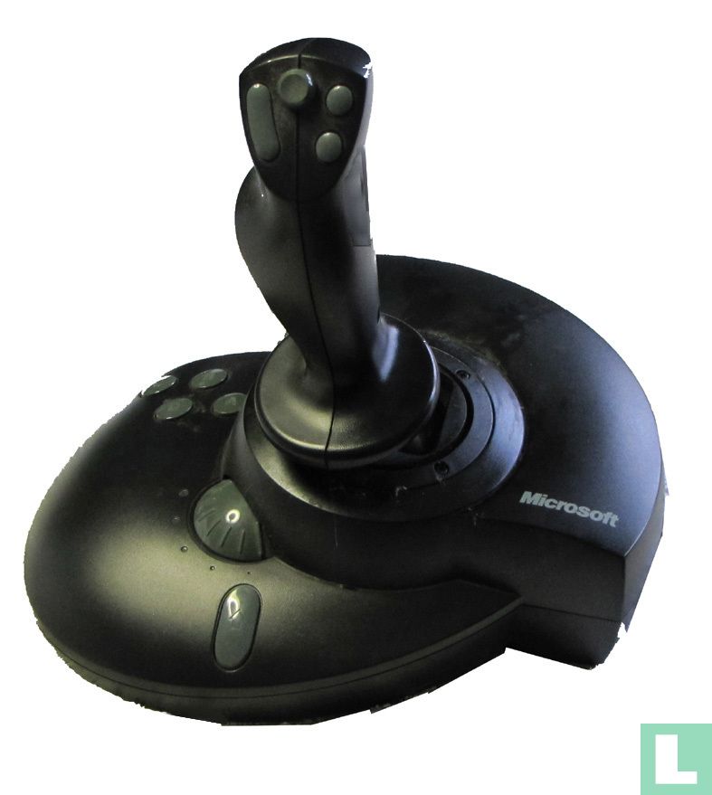
But, the biggest reason why it got neglected was the fact that Windows XP did not have drivers for this. When I left it, I remember the DC-in jack had broken off, the trigger and some buttons were worn out. It's a Microsoft Sidewinder Force Feedback Pro. Last time I used this, I think was in the late 90s when I still lived there. Recently I came across this old joystick in a closet in my parent's house.


 0 kommentar(er)
